In principle, a MFM Encoder works exactly the other way round like the MFM Decoder described in the chapter 1.7.
A MFM Encoder works according to the principle of time shifting and phase shifting. This method is based on the transmitting frequency and the MFM signals are generated in connection with the double transmitting frequency. More details concerning the MFM can be obtained from several sites in the Internet .
In the meantime, I have got used to the hardware description language Verilog at my RL02 simulator project very well. My ready developed MFM-ENCODER is obvious in the version V1.2 with a detailed description here.
The
MFM Encoder at my RL02 simulator project works with a transmitting
frequency of 4.1 MHz. The
necessary 8.2 MHz are created via divider with an input frequency
of 16.4 MHz. The 16.4 MHz are conditional historically since at my
MAXII CPLD either these MFM encoder came to use, no PLL was
available, though, so that the frequency had to be created with an
external oscillator.
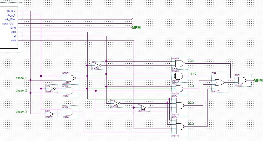
In
the following picture the real one part of the Encoder is
represented as a schematic circuit diagram for everyone who
prefers this graphic rendition comparing to a Verilog
implementation.
Development
process:
The
development based on blockdiagram with individual components and
gates got more problematic and inefficient. I have given up this
kind of development and replaced most of my modules by Verilog
programs. The
individual steps at the development of the MFM encoder also are
shown to complete this section:
A)
First
development with wiring block diagram.
B)
Second
development
with wiring block diagram
and
Verilog module.